
Install it right, once.
A wall-mounted EMS-ESS system goes up like a flat-screen TV: three color-coded cables, foolproof sockets and IP67 port insulation, with the battery terminals held at 0 V until the unit is assembled. This guide covers wiring, placement and power-on.
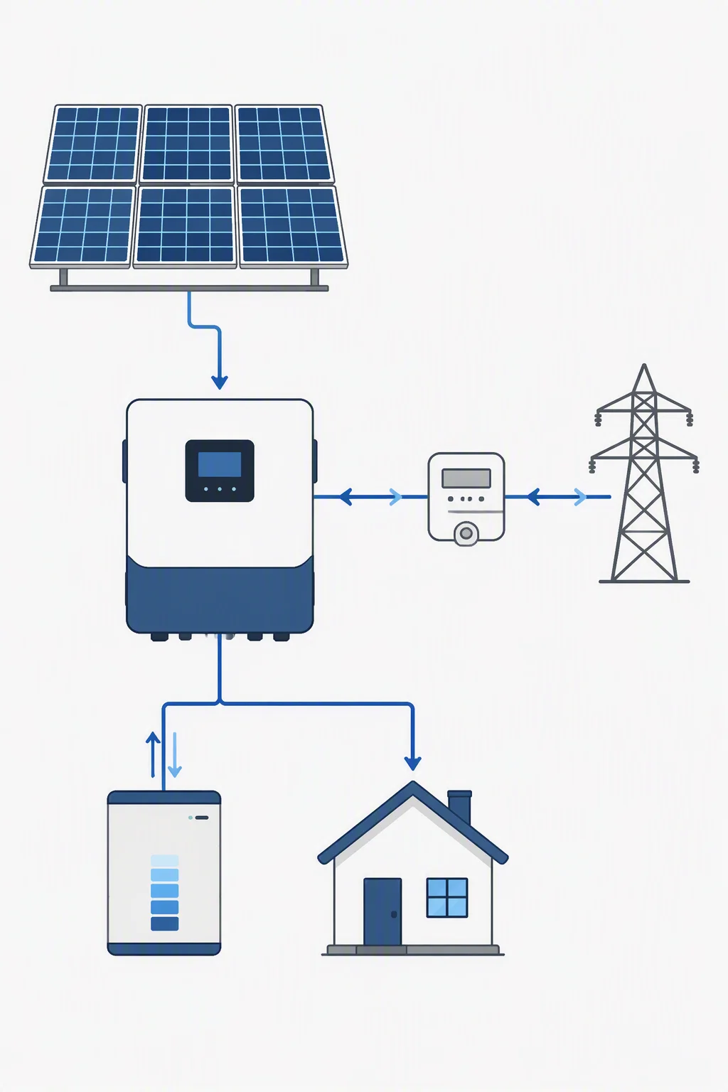
Three cables, no reverse polarity.
The system uses three distinct cables: a ground line, a battery link line and a communication line. Foolproof sockets make a reverse connection physically impossible, so an installer cannot plug the battery into the wrong terminal even under time pressure.
Ports are insulated to IP67 where they leave the enclosure, and the positive and negative terminals stay disabled at 0 V during transport — protecting both the shipper and the installer before the final connection is made.
- Ground line, battery link line and communication line
- Foolproof sockets block reverse-polarity shorts
- IP67 port insulation at the enclosure exit
- 0 V terminals until the system is fully assembled
The environment your unit needs.
Values below come from the product specification; where a figure is site-specific, confirm with sales.
| Operating temperature | -15 °C to 55 °C |
|---|---|
| Recommended temperature | 25 °C |
| Altitude | Up to 2000 m |
| Humidity | 5–95%, without condensation |
| Ingress rating | IP20 — indoor installation |
| Grounding mode | TN |
| Wall-mount load | Bracket must carry the 54 kg battery module |
| Ventilation | Clear space around the enclosure |
| Three-cable color code | Ground · battery link · communication |
| Foolproof sockets | Prevent reverse connection |
| IP67 port insulation | Sealed at the enclosure exit |
| 0 V transport ports | Terminals disabled until assembled |
| Communication line | Link cable between stacked modules |
Position, connect, power on.
Wall positioning
Fix the bracket to a wall that carries the 54 kg battery module, level it, and keep clearance around the enclosure for airflow.
Cable connection
Plug the three color-coded cables — ground, battery link and communication — using the foolproof sockets.
Power-on self-test
Switch on and read the SOC breathing light: blue, green and yellow show state; red signals a fault to check before handover.
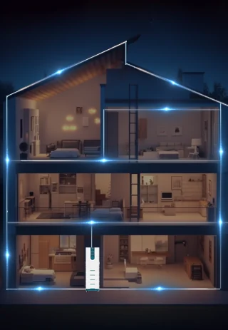
Wiring reference diagram.
Three questions installers ask.
The hybrid system carries an IP20 rating and is designed for indoor installation — a utility room, garage or plant room within the -15 °C to 55 °C operating range. For outdoor or exposed locations, contact sales to confirm enclosure and environment options.
Basic hand tools for the wall bracket, plus the three plug-in cables. The foolproof sockets remove the need for polarity checks, and the unit is designed for roughly a 5-minute mechanical assembly once the wall is prepared.
The system uses TN grounding as standard, with a dedicated ground line in the three-cable set. Confirm the local earthing scheme with your electrician; the ground connection must be made before the battery is energized.
Want the full installation manual and drawings?
Request English manuals, wiring diagrams and dimension sheets — our team replies within 24 hours on working days.