
GTB400 400 W Grid-Tie Microinverter.
The single-panel unit: one MC4 pair for one 400 W module, 400 W AC output on a 120 V or 230 V grid, with 95% peak efficiency and WiFi cloud monitoring.
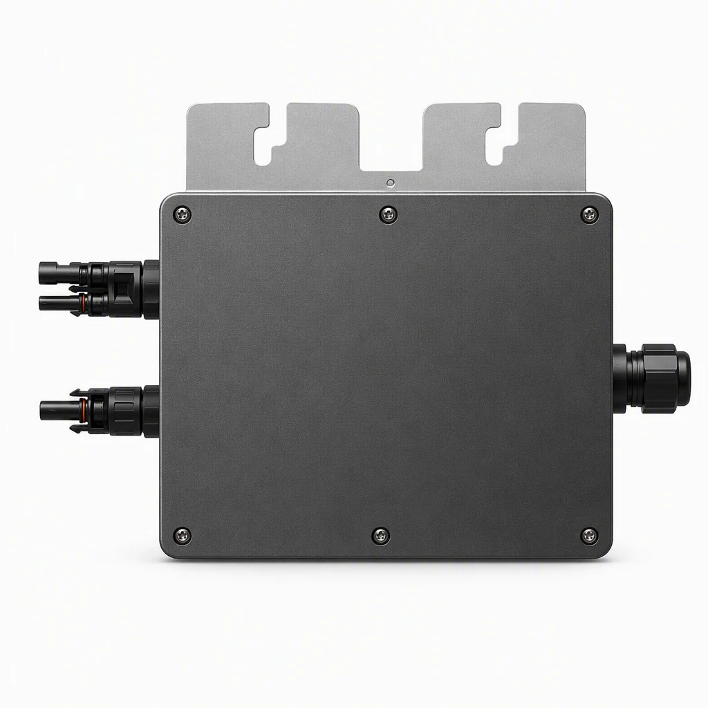
One panel, one inverter.
The GTB400 mounts behind a single 400 W module and converts at the panel, so partial shading on one module never drags down the rest of the array. It is the lightest unit in the series at 1.2 kg and the most compact at 185×160×40 mm.
- 1 MC4 pair · 12 A maximum input current
- 95% peak efficiency · 99.5% MPPT efficiency
- <1 W night consumption
- IP65 · natural convection, no fans
| Rated power | 400 W |
| MC4 | 1 set |
| Panels | 1 × 400 W |
| Weight | 1.2 kg |
| Dimensions | 185×160×40 mm |
| Per branch (230 V) | 10 units |
Every figure from the user manual.
Transcribed from the GTB400 user manual, parameter page. Warranty term is not stated in the manual, so we do not quote one.
| Number of Input MC4 Connector | 1 set |
|---|---|
| MPPT Voltage Range | 22V–48V |
| Operation Voltage Range | 20V–50V |
| Maximum Input Voltage | 52V |
| Startup Voltage | 22V |
| Maximum Input Power | 400W |
| Maximum Input Current | 12A |
| Panel configuration | 1×400W (max DC input 400W) |
| Single-Phase Grid Type | 120V & 230V |
| Rated Output Power | 400W |
| Maximum Output Power | 400W |
| Nominal Output Current | @120VAC: 5A / @230VAC: 2.6A |
| Nominal Output Voltage | 120VAC / 230VAC |
| Default Output Voltage Range | @120VAC: 80V–160V / @230VAC: 180V–270V |
| Nominal Output Frequency | 50Hz / 60Hz |
| Default Output Frequency Range | @50Hz: 48Hz–51Hz / @60Hz: 58Hz–61Hz |
| Power Factor | >0.99 |
| Total Harmonic Distortion | <5% |
| Maximum Units per Branch | @120VAC: 5 / @230VAC: 10 |
| Peak Efficiency | 95% |
| Nominal MPPT Efficiency | 99.5% |
| Night Power Consumption | <1W |
| Operating Ambient Temperature | -40 ℃ ~ +65 ℃ |
| Storage Temperature | -40 ℃ ~ +85 ℃ |
| Dimensions (W×H×D) | 185mm × 160mm × 40mm |
| Weight | 1.2 kg |
| Max Current of AC Bus Cable | 20A |
| Waterproof Grade | IP65 |
| Cooling Mode | Natural Convection – No Fans |
| Communication | WIFI (cloud monitoring) |
| Transformer Design | High Frequency Transformers, galvanically isolated |
| Protection Functions | Island / Voltage / Frequency / Temperature / Current |
| Design Compliance | EN IEC61000-3-2:2019+A1:2021 · EN 61000-3-3 · EN IEC55014-2:2021 |
| Certifications | CE · ISO9001 · ISO14001 · LVD · RoHS · IEC |
PV array to hybrid inverter.
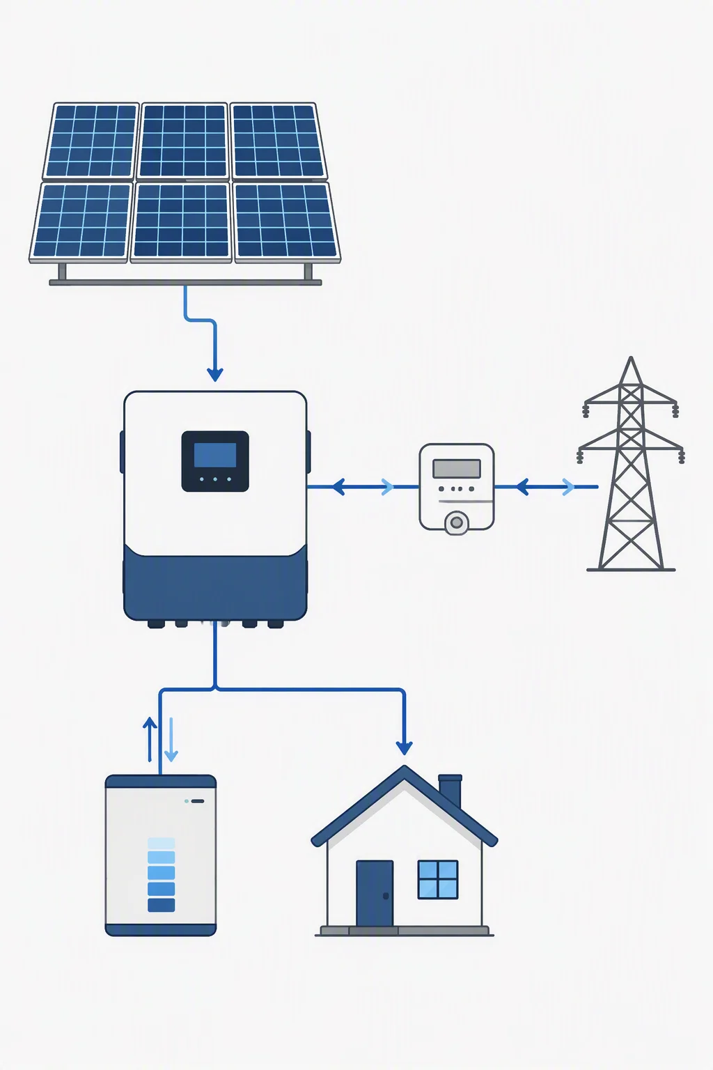
Three rules before you mount.
Check panel voltage
Keep panel Voc at or below 52 V and panel power at or below 400 W — the unit's maximum input voltage and power.
Mount out of direct weather
The housing is IP65, but the manual directs installers to avoid direct sunlight and rain and never cover the unit.
Seal unused ports
Close any unused connectors, and only qualified personnel may open the cover for service.
GTB400, answered.
One 400 W panel per unit, wired to the single MC4 pair. Keep the panel's open-circuit voltage at or below 52 V and total input at or below 400 W.
Up to 10 units per branch on a 230 V grid, or 5 per branch on a 120 V grid, per the datasheet table. The AC bus cable is rated 20 A.
Grid-tie only. The unit produces when 20–50 V DC and AC grid are both present; with PV alone the status light is red and the unit does not operate. Monitoring is via the Smart Life app over WiFi.
Quote a GTB400 run.
Send your panel wattage, quantity and grid voltage — we return a per-branch layout within one working day.